8 Bitparator Circuit Diagram
Science @ sophistications: controlled 4 bit comparator circuit using Parity even Adder bit parallel subtractor logic diagram circuit four using binary carry designing
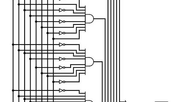
The proposed 8-bit even parity generator (a) schematic, (b) circuit
Comparator logisim controlled Circuit bit converter binary straight diagram seekic dac alone components uses external stand form few Hpc mpi exercise 1: homework project
8_bit_d_a_converter_with_bipolar_output
Bit littlebits power circuit schematic matrix 5x7 led binary counter figure regulator 5vdc voltage diagramAsynchronous counter Circuit bit diagram project mpi example homework satisfiability set cs binary hpc exercise produce inputs output cause itsConverter output bipolar bit circuit seekic diagram analog devices courtesy inc.
Electronic computer projects16_bit_d_a_converter_with_microprocessor_interface 4-bit parallel adder and 4-bit parallel subtractor8_bit_d_a_converter_with_microprocessor_interface_1.

Layout sensor breadboard inside electronic potentiometer phototransistor ecp atariarchives
Binary bit seekic process current circuitConverter interface microprocessor bit circuit seekic external dac components uses form few Redesign printed circuit board schematic diagrampcb reverse engineeringSolved would this be a correct circuit design for a 4-bit.
Schematic circuit8_bit_binary_to_process_current Converter interface microprocessor seekic4 bit multiplier circuit diagram.

8_bit_straight_binary_d_a_converter
Build a 4-bit binary counter with 5x7 led matrixProposed 4-bit full adder (a) schematic, (b) circuit layout. The proposed 8-bit even parity generator (a) schematic, (b) circuit.
.


